
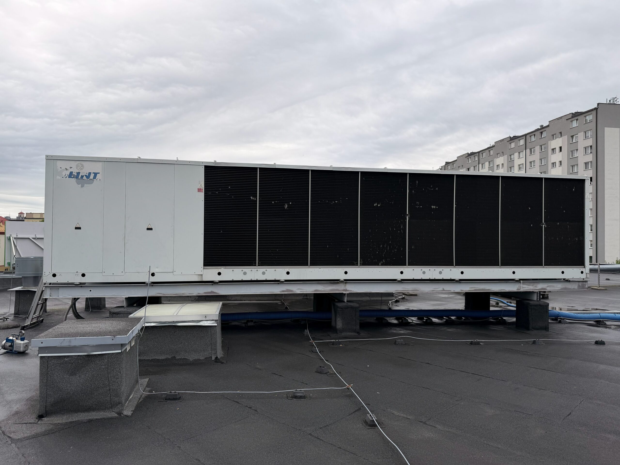
Refrigeration system design
Refrigeration system design for industrial cooling and chilled water: we calculate the load, select the units, design the pipework, free cooling and controls, build the system and commission it. One team from the first calculation to the first report.
F-gas company certificate. A report with measurements after every visit. Mobile service in Poland and the EU.
Why design matters for a maintenance team
Most of the recurring faults we are called to in existing plants were built in at the design stage: a chiller oversized for a small night load and cycling every few minutes, a buffer tank that is missing, pumps selected without a real pressure drop calculation, or glycol added afterwards without correcting the capacity. In refrigeration system design we therefore start from the way the plant will actually run and be serviced, not only from the peak load on paper.
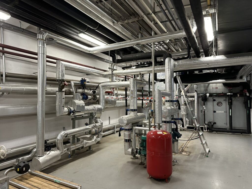
Load calculation and unit selection
For process cooling, the load is calculated from the equipment itself. For water, heat load in kW equals mass flow in kg/s multiplied by 4.19 and by the temperature difference. A circuit with 5 m3/h and a 5 K difference carries about 29 kW. We collect these data per machine, apply a realistic simultaneity factor and add a margin for planned extensions, typically 15 to 20 percent, instead of doubling the load “to be safe”.
- Temperature levels: 6/12 °C for building cooling, 10/15 °C or 15/20 °C for many machines, -5 °C and lower for glycol processes.
- Part load profile: night, weekends, winter. This decides the number of compressors and whether an inverter is needed.
- Glycol correction: a 30 percent mixture reduces the capacity of the evaporator and raises the pumping power, so the selection is made for the real medium.
- Redundancy: N+1 units or at least two refrigerant circuits where a stop would halt production.
- Installation conditions: ambient design temperature, noise limits, access for cranes and service.
Refrigerant choice
Regulation (EU) 2024/573 makes the GWP of the refrigerant a design parameter. It affects the leak check interval, future service restrictions and in some cases the possibility of placing the equipment on the market at all.
| Refrigerant | GWP | Typical use in our designs |
|---|---|---|
| R32 | 675 | Air-cooled scroll chillers and heat pumps, small and medium capacity |
| R454B | 466 | Replacement for R410A in new scroll units |
| R513A | 631 | Screw and centrifugal chillers, replacement for R134a |
| R290 (propane) | 3 | Outdoor packaged chillers with zoning and safety measures for a flammable refrigerant |
| R744 (CO2) | 1 | Commercial and industrial refrigeration, heat recovery at high temperature |
| R717 (ammonia) | 0 | Large industrial plants with machine room and trained operators |
Pipework, hydraulics and free cooling
We size chilled water pipes for velocities of roughly 1 to 2 m/s and pressure drops in the range of 100 to 300 Pa per metre, then select pumps for the calculated duty point rather than from a catalogue range. A buffer tank is included when the system water volume is too small for the minimum compressor run time; for scroll units a common starting point is 3 to 5 litres per kW of the smallest capacity step, checked against the manufacturer’s data. Our chilled water installations team builds the design in steel, stainless steel or press-fitting systems.
Free cooling is worth analysing whenever the return temperature of the process is above about 15 °C. A dry cooler can then remove all or part of the heat whenever the outdoor air is a few kelvin colder than the return water, and in Central European climates this covers a large part of the year. The design includes the three-way valve logic, frost protection with glycol and the changeover rules. Service of these units is described on our dry cooler service page.
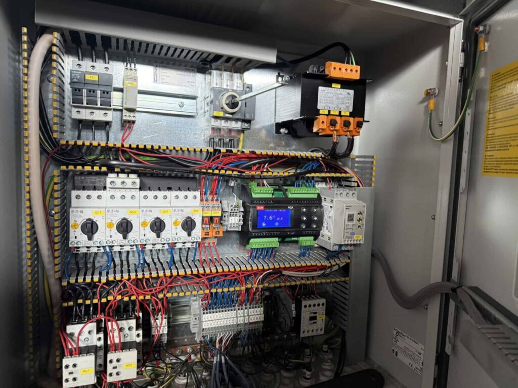
Controls
We build control panels with Siemens PLCs and HMI panels, with sequencing of chillers and pumps, free cooling logic, run hour equalisation and alarms sent by SMS and e-mail. Web visualisation lets the maintenance team see temperatures and alarms without walking to the plant room. Details are on the controls and remote monitoring page.
From design to commissioning
- Site survey and collection of process data.
- Concept with load balance, unit selection and a budget estimate.
- Detailed design: schematics, pipework routes, pump and valve selection, control description.
- Installation, brazing to EN 13585 and pressure testing.
- Flushing, filling, glycol concentration check and venting.
- Commissioning with measurements under load, setting of safety devices and controls.
- Handover: documentation, F-gas equipment records, operator training and a maintenance plan.
New and refurbished chillers can be supplied through our partner company ChillerTech, and the plant is then serviced by the same team that built it. If you are modernising an existing system, our process cooling page shows typical retrofit solutions.
Questions from maintenance teams
Can you design an extension of an existing plant?
Yes. We first measure the existing units and the actual load, because extensions designed from old drawings often duplicate capacity that is already there.
Do you design with natural refrigerants?
Yes, where the application and the site allow it. Propane and CO2 units require additional safety measures and trained service, which we include in the design and the maintenance plan.
Is free cooling always profitable?
Not always. It pays back when the process runs all year and the return water is warm enough. For a 6/12 °C building system with low winter load the gain is much smaller, and we show the calculation before you decide.
Who takes responsibility for pressure equipment requirements?
Our team holds UDT qualifications for pressure equipment and prepares the documentation required for registration and inspections where the equipment falls under them.
Planning a new cooling system?
Send us the process data or a short description of the plant, and we will propose a concept with a budget estimate.